Compiled from the supplied abbreviation lists, earlier revisions and the CCCP/CMS documents. Meanings can vary by system; use the context shown with each entry.
LAN/WAN · FIELD REFERENCE
LAN/WAN
PUBLIC ADDRESS & VA
Choose a PA system
Begin with the complete system layout, then open the relevant equipment family.
ASLVAR routers, ANS, BMB01 and amplifier systems⌄
Baldwin BoxallBVR routing, amplification and associated peripherals⌄
VipediaASL Vipedia routing and associated peripherals⌄
MICA3
Overview
MICA CLASSIC
Overview
Classic reference: the debug guide covers legacy releases 1C–2e. Confirm the fitted build, device and station drawings. Collect evidence before a restart or configuration change.
CONTROL CENTRES
Central Line SCC — Wood Lane
SYSTEM OVERVIEW
System architecture
Select a formal block diagram to understand the principal equipment and signal paths.
SYSTEM DIAGRAM
Overview
1 / 1
The diagram could not be displayed. Reconnect briefly and reopen this overview so it can be stored for offline use.
SYSTEM FAMILIES
What this overview covers
EQUIPMENT REFERENCE
Equipment
Select an equipment family, then choose a device to open its visual reference.
Tap lid to reveal internalsMANUAL VERIFIED
EQUIPMENT
Select a device
Manufacturer-backed field reference.
LABELLED COMPONENTS & FIELD POINTS
Select a labelled component or field point.
Manufacturer-backed facts are taken from the supplied manuals and training material. Tap any equipment image to open the full view, then swipe left for its numbered descriptions or field notes.
ASL VAR ROUTER
Alarm index
Select the displayed message to expose the components implicated in that fault. Verified routes then continue into guided diagnosis.
Guided route ready Components indexed
Index verified against the supplied ASL PA/VA Fault Finding Guide Issue 1.1 and Router Handbook Issue 2. Display wording and available codes can vary with VAR software and site configuration.
ASL REMOTE I/O
BMB01
Front, internal, circuit and wiring reference.
Do not confuse the pull-upsLK4 and LK5 enable pull-ups for digital-input opto-isolators. Each analogue input AI1-AI12 has its own fixed internal 4.7 kΩ pull-up to +5 V; those twelve resistors are not enabled by LK4 or LK5.
RS485
BMB01 to VAR4 EXP1
EXP1 shown looking directly at the male connector on the rear of the VAR4.
50DATA DXPRS485 +
51DATA DXNRS485 -
490V INReference
52SCREENChassis
VAR4 EXP1
123456789
Pin 3: 0V · Pin 5: DXP · Pin 9: DXN
BMB 52 screen terminates to the VAR/chassis screen connection; it does not replace the pin 3 data-reference conductor.
PUBLIC ADDRESS & VA
Ambient Noise Sensors
ANS04E / ANS04-ES with BMB01 and VAR4
LAB VERIFIED
Open ANS control circuit → REM01 AIN01 FAULT → configured output forced to maximum.
KNOWN SYMPTOMS
Choose what you see
GUIDED CHECK
REMxx AINyy FAULT
Use measurements to narrow the physical cause.
Safe measurementVoltage: meter in parallel. Current: meter only in series. Isolate before resistance checks or wiring changes.
Step 1 of 5
QUICK REFERENCE
ANS04E wiring & readings
Manufacturer specifications plus clearly marked lab observations.
With the ANS output open, the BMB's internal 4.7kΩ pull-up and external 235–240Ω resistor form a divider:
5 V × 240 ÷ (4700 + 240) ≈ 0.243 V
This is an invalid low signal. The VAR reports the analogue-input fault and applies the configured fail-safe action.
PHP REFERENCE
Engineers Briefing Notes
20 supplied notes covering Audiocom, ASCOM NIS2000 and Commend systems. Select a note to see its scope and open the full document.
These are supplied engineering references, not confirmation of the current controlled issue. Check the installed equipment, firmware, site configuration and approved work instructions before using a procedure. Preserve the as-found configuration before authorised changes.
PLATFORM HELP POINTS · COMMEND
Inside the PHP
Explore the passenger controls, ET808 station electronics, DC15 supply, AFIL amplifier and door components.
Safe measurementMeasure voltage live only when the approved task requires it. Isolate and disconnect the component before resistance or continuity checks.
SELECT A CONTROL
Passenger-facing controls
Tap a button to see the contact path and its GE700 function.
Standard PHPInformation and emergency calls
Tap image to enlarge
PHP with fire alarmBreak-glass interface fitted
Tap image to enlarge
SELECT A COMPONENT
Electronics and open door
Tap a highlighted part. Connected wiring and the receiving board will illuminate.
Electronics enclosureET808 LINE input, AFIL and DC15
Tap image to enlarge
Open doorPassenger controls and audio
Tap image to enlarge
SELECTED PATHChoose a component to trace its connection.The corresponding board and wiring path will highlight.
The PA700 supplies the GE700 CEU power path. The separate PSU005 is the distributed PHP supply: nominal 42.4 V DC, up to twelve PHPs and a maximum 300 m cable route to each PHP. Confirm circuit labels before isolation or measurement.
ROUTE INDEXED
Coming next
The structure is ready. Verified fault routes, drawings and field readings can be added without redesigning the app.




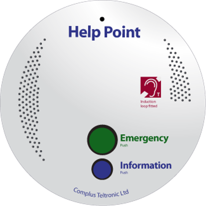 Tap image to enlarge
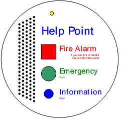 Tap image to enlarge
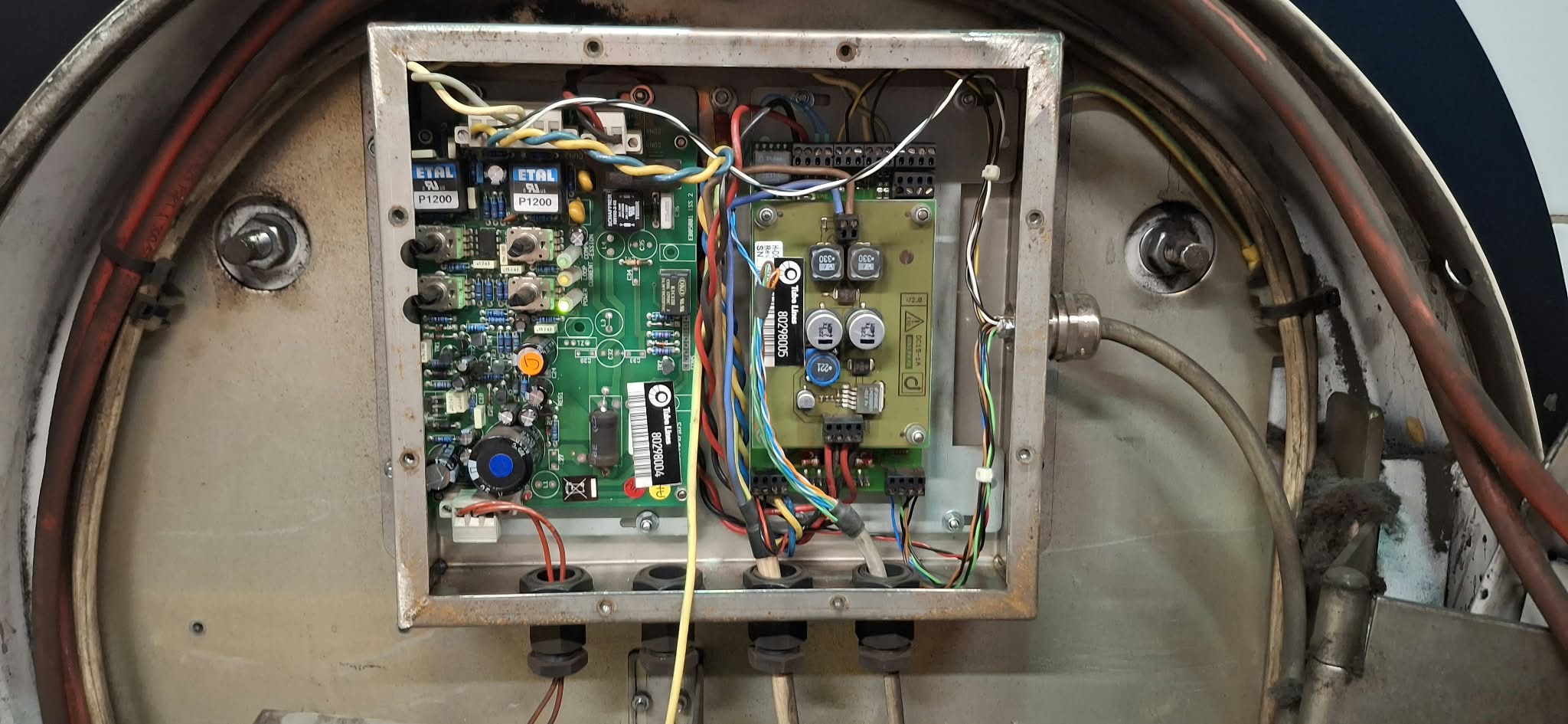 Tap image to enlarge
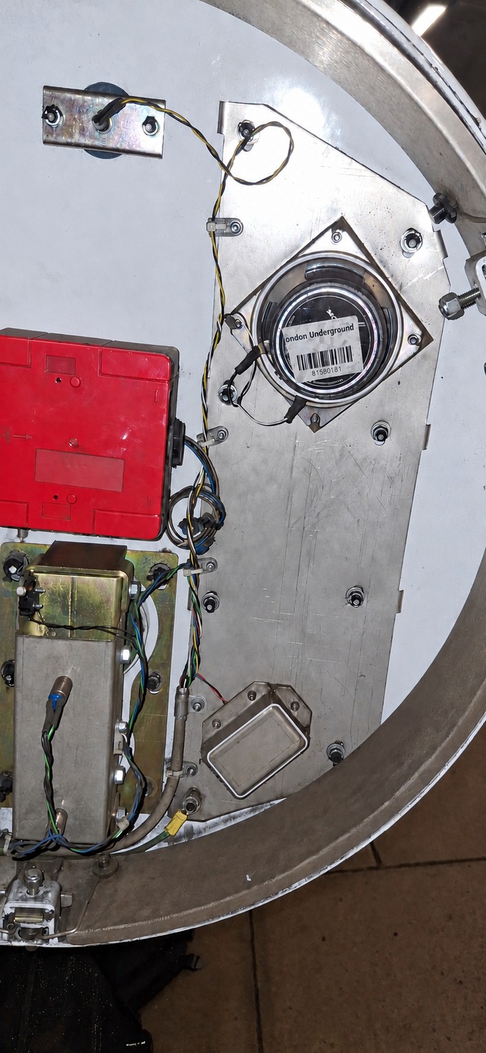 Tap image to enlarge